


Custom Personnel Lifts, Drive-On Scissor Platforms & Test Benches for Aerospace Facilities: What's Possible
If you've searched for a drive-on scissor lift bench, a custom personnel lift for an aerospace machining center, or a scissor lift with leak containment, you already know the catalog doesn't carry what you need. These aren't rental-yard machines. They're engineered configurations: platforms sized to your test article, decks that catch hydraulic fluid before it reaches the floor, and lifts that sit flush with the slab until the work order calls for them.
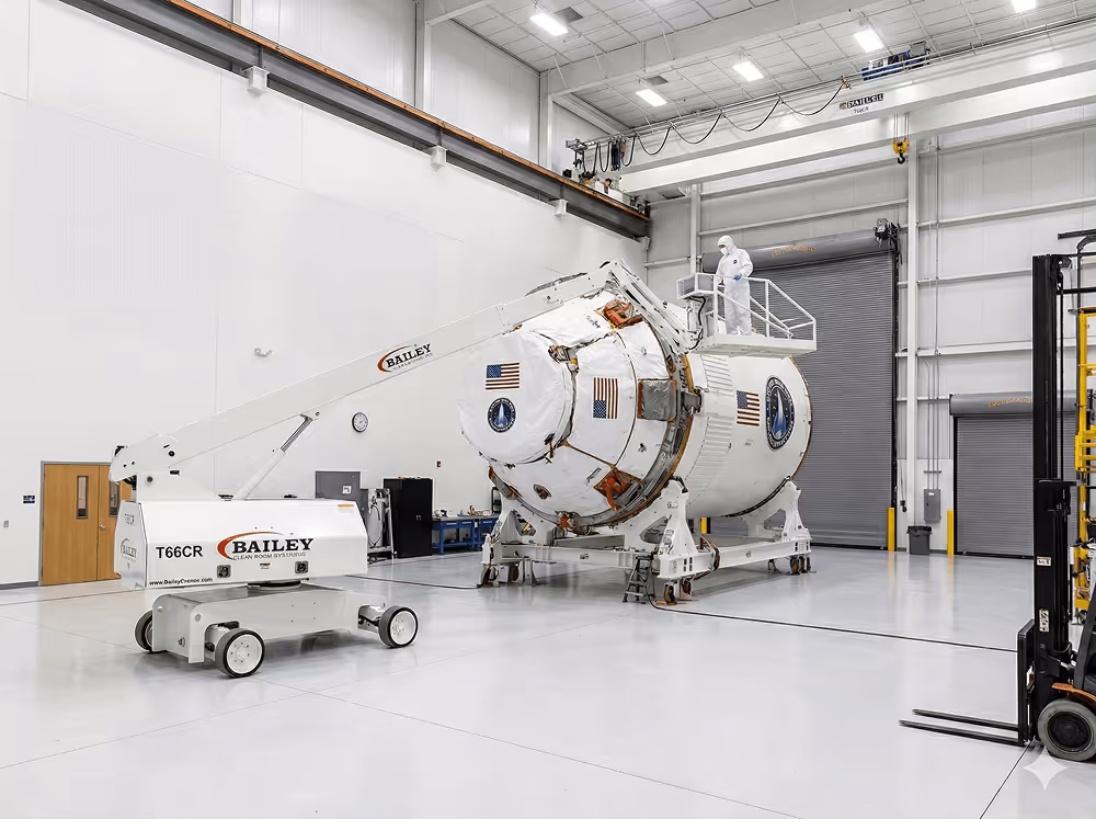
This guide walks through the custom personnel-lift and platform configurations aerospace facilities actually commission — drive-on scissor benches and test platforms, leak-containment decks, in-floor lifts, machining-center access lifts, and the environment packages that adapt each one for outdoor, cleanroom, or hazardous locations — along with the constraints that govern every one of them: capacity at configuration, deck size, floor loading, and containment volume. Bailey Cranes engineers and builds these configurations in Muskego, Wisconsin for aerospace OEMs, MRO operations, and defense facilities.
Why Aerospace Work Orders Outgrow Catalog Lifts
Aircraft geometry, machining-center envelopes, and contamination rules produce access problems no standard scissor lift solves. A catalog machine assumes a flat, open floor, a standard working height, and no restrictions on what its tires, hydraulics, or chassis are allowed to touch. Aerospace work violates those assumptions constantly: the task happens over a wing skin, inside a machine tool's working envelope, above a slab that can't take the point load, or in a bay where a single drop of hydraulic oil is a reportable event.
We've already made the business case for engineering the lift around the job instead of bending the job around a lift — see the ROI case for custom lifts and when off-the-shelf equipment isn't enough. This post is the what, not the why: the configurations that show up in aerospace RFQs again and again, and the specifications that determine whether each will work in your facility.
Drive-On Scissor Platforms and Test Benches
What a Drive-On Scissor Bench Is and How It Works
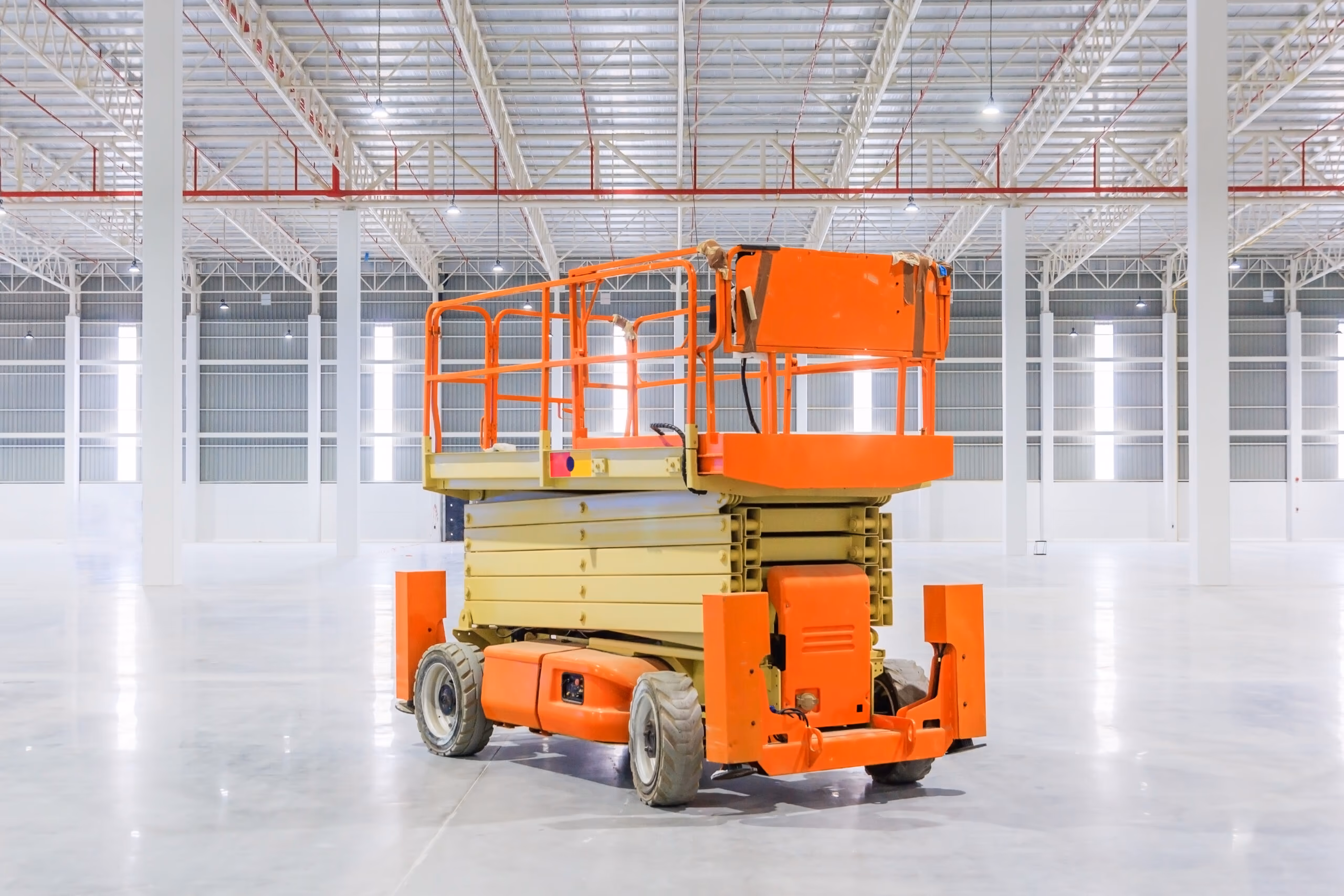
In short: a drive-on scissor bench is a scissor-lift platform with ramp or floor-flush access, so carts, fixtures, and wheeled test articles roll directly onto the deck — and then the entire deck elevates the load and the people working on it to working or test height. It replaces the crane-and-rigging step that normally stands between a wheeled load and an elevated workstation: no slings, no re-rigging, no waiting on the overhead crane schedule.
Access comes in two forms. A ramp-loaded bench uses a fixed or fold-down ramp; the governing details are ramp angle against the cart's ground clearance and the push force your team (or tug) can apply. A flush-loaded bench sits in a shallow pit so the lowered deck meets the floor with no ramp at all — which is where drive-on benches overlap with the in-floor lifts covered below.
Read the capacity line twice. A drive-on platform carries three separate ratings that are easy to conflate: the static rating (what the deck holds once parked), the roll-on rating (the dynamic load the deck and scissor take while the cart is moving across it), and the wheel point-load (the force each cart wheel concentrates on the deck plate). The roll-on rating and point-loads govern the design — not the headline number. Mechanical deck locks that carry the load during long work sessions, rather than leaving it on the hydraulic circuit, are standard practice on benches people occupy.
Single vs. Double (Dual-Stage) Scissor: When You Need the Second Stack
A double — dual-stage — scissor stacks two scissor mechanisms on one base. The second stack buys travel: roughly double the lift height from the same footprint, so a deck can climb high without the longer arms and larger footprint a single-stage unit would need. The price shows up in three places: a taller collapsed stack, because two nested arm sets have to fold under the deck instead of one; reduced stiffness and a capacity derate at full extension; and cost.
The decision rule is simple: let travel requirement and footprint drive the choice. If the deck must climb high from a tight footprint, the double scissor earns its keep. If pit depth is the tight budget, or deck rigidity under roll-on loads is the priority, a single-stage — or a purpose-designed low-profile scissor — is the stiffer, simpler answer.
Test Platforms and Test Benches for Aerospace Components
The test-stand variant elevates a component plus its instrumentation to a fixed, repeatable height and holds it there. That shifts the spec conversation from mobility to precision: leveling tolerance across the deck, hard stops or shot pins for repeatable elevation, vibration behavior under running equipment, and guarding for technicians who stay on the deck during the test. Utilities are the detail teams forget — compressed air, power, and data can be routed through the scissor so the bench arrives at test height already connected, with no cable service loop dangling to the floor.
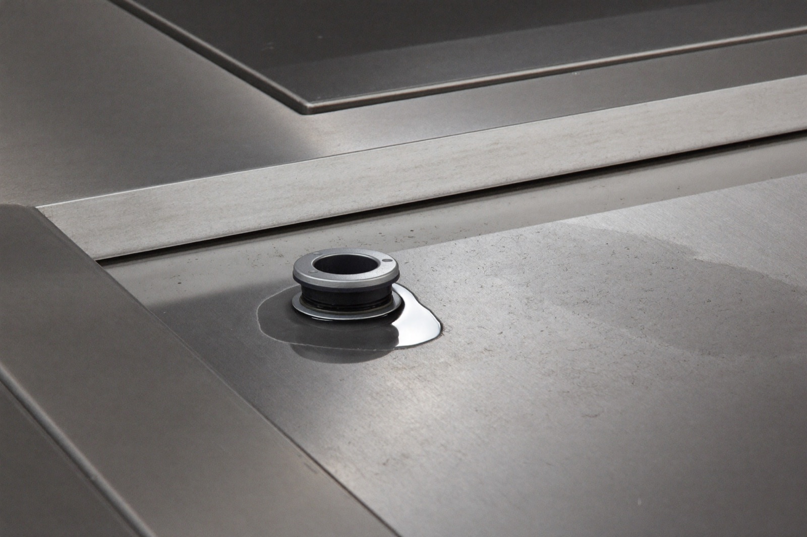
Leak and Drip Containment Decks: Lifting Where Fluids Can't Touch the Floor
Aerospace facilities spec containment because the fluids involved — Skydrol and other phosphate-ester hydraulic fluids, fuels, and cutting coolant around machining centers — are either aggressive, reportable, or both. When the equipment on the platform can leak, the platform has to catch it.
There are two engineering answers, and serious specs usually combine them. The first is containment built into the deck: a recessed tray under the work surface with a raised coaming lip and a valved drain fitting for controlled recovery. The sizing math is blunt — containment volume must meet or exceed the worst-case fluid volume of whatever sits on the deck. A component carrying five gallons of hydraulic fluid needs a tray that holds at least five gallons, plus margin for wash-down. The second answer is source elimination: all-electric actuation, so the lift itself carries no hydraulic oil over the very containment it's protecting. We've compared the two drive philosophies in detail in our hydraulic vs. electric scissor lift guide, and our EX scissor platforms show how far all-electric design can go.
In-Floor and Pit-Mounted Personnel Lifts
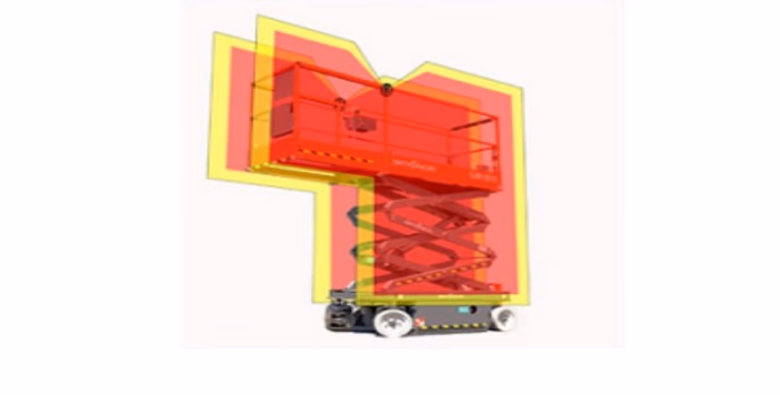
An in-floor lift takes the ramp out of the equation entirely: the deck sits flush with the surrounding slab when lowered, so carts, tugs, and foot traffic cross it like ordinary floor — until it rises. For high-traffic aisles and machining cells where a parked lift would block circulation, flush-mounting is often the only configuration the layout allows.
Four design inputs govern a pit installation. Pit depth budget — the collapsed height of the mechanism sets how deep the pit must be, and this is where the single vs. double scissor choice bites: a dual-stage stack folds taller, so it needs a deeper pit, and shallow-pit projects push toward single-stage or low-profile designs. Edge and gap guarding — toe protection and gap closure where the rising deck separates from the floor. Pit housekeeping — drainage and FOD control, because everything on the floor eventually finds the pit. And slab capacity — a pit-mounted unit transfers its loads into the slab edge and pit floor, which makes the concrete itself a design input. That last one deserves respect: we've written up how we solved a floor-loading problem for a major aerospace OEM when the slab, not the lift, turned out to be the hard constraint.
Personnel Lifts for Aerospace Machining Centers
Large 5-axis machining centers and gantry mills create a specific access problem: operators need repeatable, safe access to spindles, tool changers, and gantry rails — inside the machine's envelope, around chip conveyors and coolant tanks, without anchoring anything to the machine itself. Ladders don't reach, catalog scissor lifts don't fit between the ways, and nobody wants a lift tire on a machine foundation.
The configurations that solve it: fixed-position or rail-guided personnel lifts that travel a defined path alongside the machine, cantilevered decks that reach over machine beds so the wheels stay outside the envelope while the platform doesn't, and coolant-resistant decking and finishes for the mist and chips that come with the territory. The same thinking applies at aircraft scale — our post on custom platforms and MRO downtime covers the airframe-access side of the problem.
Environment Packages: Outdoor, Cleanroom, and Explosion-Proof
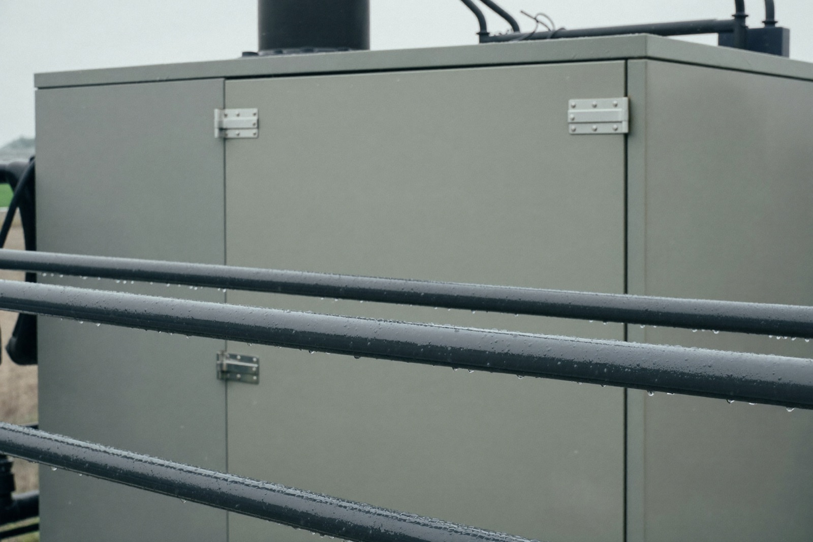
Weather-Resistant Personnel Lifts for Outdoor Yards and Flight Lines
Yes — personnel lifts can be built weather-resistant for permanent outdoor service in industrial yards and on flight lines. The package that makes it work: NEMA 4/4X-rated controls and enclosures, sealed electric actuators, self-draining deck surfaces, marine-grade coatings on the structure, and temperature-rated batteries and hydraulics for cold-weather operation. That's a different animal from a rental machine that tolerates rain — catalog lifts are generally rated for intermittent outdoor exposure, not for living outside.
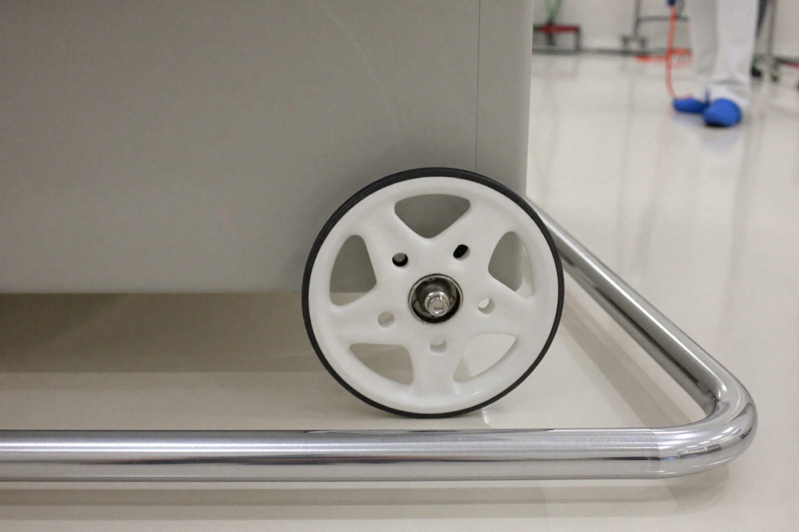
Cleanroom and EX-Rated Versions of Every Configuration Above
Every configuration in this post — drive-on benches, containment decks, in-floor lifts, machining-center lifts — can carry a cleanroom package (ISO-class materials, non-marking tires, sealed drives) or an explosion-proof (EX) package rated for Class I, Division 1 or Division 2 hazardous locations — with protection methods matched to the division — for fuel-cell maintenance and paint-hangar work. The environment rating is specified at design time, not retrofitted. The depth on both lives on our product pages: clean room man lifts and explosion-proof lifts.
Custom Crane Baskets and Personnel Platforms for Existing Cranes
Sometimes the answer isn't a new lift at all — it's an engineered personnel basket or platform for a crane you already own. These are not welded-up shop projects: ASME B30.23 governs personnel platforms on cranes, with specific design factors, attachment requirements, and proof-testing. Within those rules there's real room to engineer for the work: contoured baskets that nest against fuselage and wing profiles without contact, integrated tool trays, and padded rails for work beside finished surfaces. Our attachments and add-ons line shows the range.
The Constraints That Govern Every Custom Lift
Every configuration above lives or dies by the same handful of constraints. Bring numbers for each of these to the first engineering conversation and the project moves fast; leave them undefined and the concept phase stretches.
- Capacity at configuration. Static, roll-on/dynamic, and point-load ratings are different numbers. Spec the load path, not the headline.
- Deck size vs. footprint vs. access. The deck the work needs, the footprint the floor allows, and the doorways and aisles the unit must pass through on its way in.
- Floor loading. Wheel loads and scissor-base point loads against the slab's actual rating — the constraint most projects discover last.
- Containment volume. Worst-case fluid volume of everything the deck will carry, plus wash-down margin.
- Travel height and collapsed height. Together these choose single vs. double scissor and surface vs. pit mounting.
- Environment rating. Outdoor, cleanroom class, or hazardous-location certification — decided at design time.
The envelopes below are representative of custom-build ranges, not catalog SKUs — every real project is engineered to its own numbers.
| Configuration | Typical capacity | Typical deck size | Lift height | Governing constraint |
|---|---|---|---|---|
| Drive-on single-scissor bench | 2,000–10,000 lbs roll-on | 6×8 ft – 8×20 ft | 3–6 ft | Wheel point-load on deck; ramp angle vs. cart clearance |
| Drive-on double-scissor platform | 2,000–6,000 lbs | 6×8 ft – 8×12 ft | 6–14 ft | Collapsed height vs. stiffness derate |
| Scissor lift with leak-containment deck | 1,000–6,000 lbs | Sized to equipment + coaming | 3–12 ft | Containment volume ≥ worst-case fluid spill |
| In-floor / pit-mounted personnel lift | 1,000–8,000 lbs | Flush deck to 8×12 ft | Pit-dependent | Slab/pit floor loading; pit depth budget |
| Custom crane basket / personnel platform | 500–2,000 lbs (personnel-rated) | 3×4 ft – 4×8 ft | Host-crane dependent | ASME B30.23 design factor; host crane derate |
What the Custom Process Looks Like (and How to Start a Spec)
Every custom program at Bailey runs the same arc: a requirements review where your loads, dimensions, floor limits, and environment rating get pinned down; concept and load-path engineering; a design review where you see the machine before steel is cut; then fabrication and load testing in Muskego. The full picture is on our custom engineering page — and if you want to rough out a configuration before you talk to anyone, build it in the customizer and send us the result.
Frequently Asked Questions
What is a drive-on scissor lift bench?
A drive-on scissor bench is a scissor-lift platform with ramp or floor-flush access so carts, fixtures, and wheeled equipment can be rolled directly onto the deck, which then elevates the load and personnel to working height. It replaces the crane-and-rigging step for moving test articles onto a bench. Aerospace facilities use them as elevating workstations and component test platforms.
What is the difference between a single and double scissor drive-on platform?
A double (dual-stage) scissor stacks two scissor mechanisms to roughly double the lift height available from the same footprint. The tradeoffs are a taller collapsed height — the two nested arm sets need a deeper pit for flush-floor installation — plus reduced stiffness and rated capacity at full height compared to a single scissor. Choose double scissor when travel height from a constrained footprint dictates; choose single scissor when pit depth is limited or deck rigidity under roll-on loads matters most.
Can a scissor lift have leak containment?
Yes — scissor lifts can be built with integral leak-containment decks: a recessed, coamed tray under the work surface sized to hold the worst-case fluid volume of the equipment on the platform, with a valved drain for controlled recovery. All-electric scissor lifts go further by eliminating onboard hydraulic oil entirely, so the lift cannot itself become the leak source. Aerospace facilities spec these for work involving Skydrol, fuels, and machine coolant.
What is an in-floor personnel lift?
An in-floor (pit-mounted) personnel lift is a scissor or telescoping lift installed in a recessed pit so its deck sits flush with the surrounding floor when lowered. Equipment and personnel move onto it with no ramp, and the deck rises to working height on demand. Pit depth, slab load capacity, and edge guarding are the governing design inputs.
Are there weather-resistant personnel lifts for outdoor industrial yards?
Yes — personnel lifts can be engineered for permanent outdoor service using NEMA 4/4X-rated controls, sealed electric actuators, self-draining decks, and marine-grade coatings. Cold-weather packages extend battery and hydraulic operating ranges for flight-line and yard use. These are custom-built configurations rather than catalog rental machines, which are generally rated for intermittent outdoor use only.
Can custom personnel lifts be certified for cleanrooms or explosion-proof environments?
Yes — drive-on benches, containment-deck lifts, and in-floor platforms can each be built to cleanroom protocols (non-marking tires, sealed drives, low-particulate materials) or as explosion-proof (EX) units rated for Class I, Division 1 or Division 2 hazardous locations, with protection methods matched to the division. Aerospace applications include fuel-cell maintenance, paint hangars, and semiconductor-grade cleanroom access. The environment package is specified at design time, not retrofitted.
How much weight can a drive-on scissor platform support?
Custom drive-on scissor platforms are commonly engineered for roughly 2,000 to 10,000 lbs of roll-on capacity, but the governing numbers are the dynamic roll-on rating and the wheel point-loads of the cart crossing the deck — not the static maximum. Facility floor loading under the scissor base is the other hard limit. Always spec from the load path, not the headline capacity.
How long does a custom-engineered lift take to design and build?
Custom lift programs run from requirements review through concept engineering, design approval, fabrication, and load testing — typically a period of months rather than weeks, depending on certification requirements such as cleanroom, explosion-proof, or personnel rating. Starting with defined loads, deck dimensions, floor limits, and environment rating shortens the engineering cycle significantly.
Next Steps
If the configuration you need appears anywhere on this page — or doesn't, which is usually the better reason to call — the fastest path is a short conversation with numbers in hand: load, deck size, floor rating, environment. Start with our custom engineering process, rough out your configuration in the customizer, or talk to our engineering team directly.
Ready to lift your service?

Additional Content
Proven Platforms. Precision-Engineered Solutions.
Partner with Bailey to transform proven platforms or build fully custom lifting solutions—engineered, manufactured, and supported under one roof for mission-critical environments where failure is not an option.